Synchronous Buck-Boost Regulator
IMPR-POW-R-01
A regulated 5.0 V rail from battery-backed power, built to sit after IMPR-POW-C-02.
Manufactured — Bring-Up
Video
Manufactured — Bring-Up
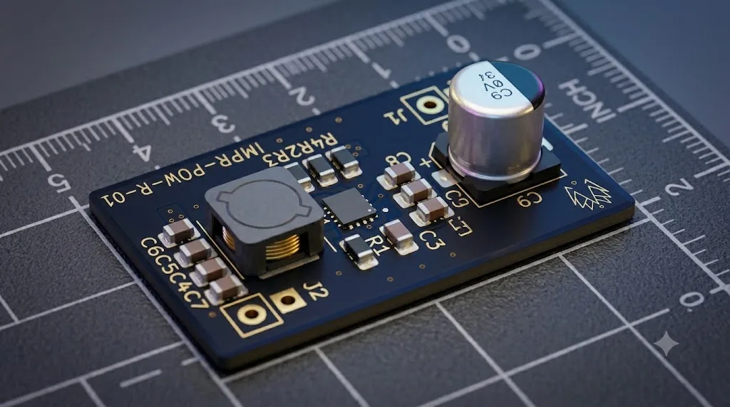
IMPR-POW-R-01 — Top view render A steady 5.0 V, whatever the battery is doing
IMPR-POW-R-01 is a compact, breadboard-compatible synchronous buck-boost regulator module built around the TPS630702. Designed to sit after IMPR-POW-C-02, it converts the protected system rail into a regulated 5.0 V output for embedded prototypes, ESP32-class boards, radio adapters, and M1 bring-up work.
Designed and manufactured by Imperium Softworks. Schematic, layout, sourcing, assembly, and bring-up are handled in-house.
How the regulator works
From system rail to a clean 5 V
Board Telemetry
Render ModeStatic Preview
Board Dimensions33.02 × 17.78 mm
Regulator ICTPS630702RNMT
Default Output5.0 V regulated rail
Component Stack
01. TPS630702
Synchronous buck-boost regulator
02. SRI0605B-1R5M
1.5 uH shielded power inductor
03. Output capacitor bank
MLCC output bank for transient support
04. Feedback network
Configured for regulated 5.0 V output
Board Profile
Input Target3.0-5.5 V system rail
Output NodeVREG_OUT
Pin Pitch2.54 mm
Pairing ModuleIMPR-POW-C-02
TPS630702 / 1.5 uH / 5.0 V
IMPR-POW-R-01
Compact buck-boost regulation for breadboard and M1 prototype power stages.
- 01 Protected system power (3.0–5.5 V) arrives on SYS_IN, typically from IMPR-POW-C-02.
- 02 The TPS630702 bucks or boosts automatically, whether the input is below, near or above 5 V.
- 03 A regulated 5.0 V rail leaves on VREG_OUT for ESP32 boards, radios and test loads.
- 04 Vertical 2.54 mm headers drop it straight onto a breadboard or into the RAD stack.
Specifications
Power Regulation
- Regulator IC
- TPS630702RNMT
- Topology
- Synchronous buck-boost
- Input Target
- 3.0-5.5 V system rail
- Default Output
- 5.0 V regulated rail
- Output Target
- 1 A-class prototype rail
Connectivity & Pinout
- Input Header
- SYS_IN / GND
- Output Header
- VREG_OUT / GND
- Connector Style
- Vertical 2.54 mm pin headers
- Pairing Module
- IMPR-POW-C-02
- Primary Load Targets
- ESP32 / LoRa-RFM95 / Test Loads
Form Factor
- Board Dimensions
- 33.02 × 17.78 mm
- PCB Stack-up
- 2-Layer PCB
- Component Mounting
- SMT + THT headers
- Pin Pitch
- 2.54 mm
Where it fits
The middle of the power stack.
- Deployed IMPR-POW-C-02 USB-C input, charging and protection upstream.
- Manufactured — Bring-Up · You are here IMPR-POW-R-01 A regulated 5.0 V rail from the protected system power.
- Field tested IMPR-RAD-01 The tactical mesh radio node it powers.
Need a custom power stage?
Ask about POW-R-01, or have the team that built it design a power stage for your product. Mutual NDA first; a full proposal with budget and timeline before any work starts.